Install the Sensor
- Undo the threaded coupler, and remove the barrel top and associated PVC pipe.
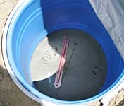
- Using a Brunton geologist's compass or equivalent, mark an orientation line along a diameter in the bottom of the barrel. Depending on the seismometer to be installed, the line should be oriented either true north or true east. Mark north or east with an arrow, and write on the concrete in the bottom of the barrel the station ID and the magnetic declination used to determine true north or east.
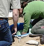
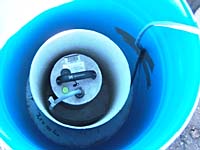
- Place the seismometer carefully in the bottom of the barrel. Align the seismometer carefully with the orientation line.
- Undo the locking nuts on the adjustable feet, and adjust the sensor for level. Check during adjustment to make sure it is still properly aligned with true north or east.
- Relock the feet, making sure level does not change.
- Connect the sensor cable to the sensor. From the sensor, the cable should run down to the bottom of the barrel before exiting at the top of the barrel, to give it more support and keep it from generating vibrations.
- If this is a seismometer with manual mass locking, unlock the sensor.
- Carefully place a "sensor hut" over the sensor. This can be any of several types; most of our installations used sections of PVC pipe slightly larger than the seismometer. For STS-2 sensors, we found that a 5-gallon plastic paint bucket works well, also. The purpose of the sensor hut is to limit convective air movement around the sensor. The cable should exit the sensor hut through a notch at the bottom.
- Attach the sensor cable to the side of the sensor vault (barrel) with high-quality duct tape. Again, the purpose is to limit vibration in the cable.
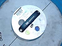
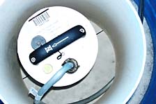
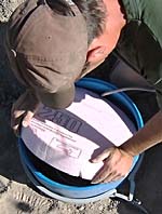
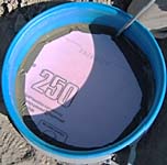
- Cover the sensor hut with one or more "cookies". These are round fillers cut from 3" builder's styrofoam, usually pink in color. The cookies should have a notch for the sensor cable.
- Use duct tape to fill the gaps around the cookie, to limit convective air flow.
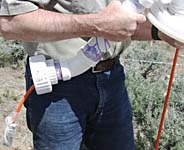
- Many broadband seismometers include a breakout box (which provides access to the signals in the sensor cable) between the sensor and the data logger. Depending on the sensor type, the cable lengths, and the distance to the electronics enclosure, it may be necessary to place the breakout box on top of the cookie. If possible, it is preferable to put the breakout box in the electronics enclosure.
- Make sure the barrel lid clamp is already on the barrel -- otherwise you may end up repeating the following steps!
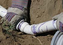
- Put a plastic bag over the sensor cable connector, secure with a bread tie or rubber band, and thread the cable through the barrel lid, through the PVC pipe, and out the threaded disconnect.
- Thread the cable through the other side of the disconnect, through the "T", and into the electronics enclosure.
- Fasten the threaded disconnect securely together, and place a foam plug in the top of the barrel to limit air flow and small creatures from getting into the barrel.
- Fasten the lid securely on the barrel. If necessary, slightly adjust the position of the electronics enclosure to make everything fit tightly together.
- Place a foam plug in the fitting inside the electronics enclosure to seal around the cables.
- Place a foam plug in the gooseneck where the solar panel and GPS cables exit.
Now we can install the electronics...

